Creating a "data tap"
-
One device that's handy when working on network problems is something called a "data tap". This is inserted between two devices and a computer running Wireshark can then be used to monitor and analyze the traffic. A data tap can be made with a managed switch. A proper data tap will not allow packets from the monitoring computer or even the tap itself to appear on the monitored connections as that can cause problems if port security is used.
Here's how to create one:
- Get a five (or more) port managed switch.
- Configure one port for the monitoring computer (I use port 1).
- Configure another port to be monitored (I use 2)
- Configure port based VLANs, with the monitoring port (port 1 in my case) on the default VLAN 1
- Configure all the other ports on another VLAN (I used 2).
- Configure port mirroring so that the monitoring port mirrors the monitored port.
- Turn off Loop Prevention.
- While the switches generally support DHCP, I configured mine to use an address in the 169.254.0.0 /16 link local range.
Once this is done, you have a "data tap". Connect a computer running Wireshark to the monitoring port and pass the monitored connection through the monitored port and any other.
Steps 4 & 5 are to prevent packets from either the switch or monitoring computer from appearing on the monitored circuit. However, I have noticed that one or two broadcast/multicast packets from the monitoring computer appear in the monitored circuit, if that computer is plugged into the switch, when the switch is powered up. So, power up the switch and connect the monitoring computer to it, before inserting the switch into the circuit to be monitored.
Step 7 stops the packets used to determine if a loop exists.
I configured the switch to use a link local (169.254.0.0 /16) address, so that it won't conflict with anything on the network. Also, a computer configured for DHCP can be plugged into the monitoring port and, when DHCP fails, will usually default to a link local address. The monitoring port can now be used for configuring the switch.
Also, while they do work, I'd advise against TP-Link switches, as some models do not handle VLANs properly, in that broadcast/multicast packets leak between VLANs. I suspect this may be why I see those packets when the switch powers up.
-
@jknott A problem I encountered is this data tap didn't pass unknown VLAN packets.
My entire purpose of creating a tap was to discover what VLAN ID's are being used between my ISP-supplied router and ISP ONT fiber modem. My managed switch (Aruba 2930F) does not accept tagged packets unless you already know the VLAN ID and tag the ports for the ID.
I couldn't find any method for my switch to accept packets with an unknown VLAN ID. I'm fairly certain it's not possible.
To work around this, I configured an unused pfSense OPT port as a standalone interface with IPv4 and IPv6 configured to NONE. I unplugged my ISP router and connected its WAN port to the pfSense OPT port. Next, I started a packet capture in promiscuous mode and powered-up the ISP router.
I was able to capture DHCP Discovery packets tagged with a VLAN ID, thus revealing the unknown ID.
This enabled me to tag the switch ports participating in the data tap with the discovered VLAN. I reconfigured my cabling to insert the data tap between the ISP router and ISP modem. This successfully provided a data tap which allowed capture of the VLAN traffic in situ.
-
My switch doesn't have that issue. I'm not familiar with that Aruba switch, so I can't comment on it. Are you saying that if you configure it without any VLAN it won't pass tagged frames. The VLAN I used in my switch was port based, not tagged, and that was only to keep the monitoring computer from interfering with the monitored circuit. Try it without any VLAN, and just port mirror 1 port to see what happens.
-
@jknott HP/Aruba are one and the same, BTW. I tagged my monitoring port 1 with VLAN 4000, and the monitored ports 2&3 with 4001. Port 1 mirrors port 2.
Packet capture shows inbound untagged traffic on port 2 with no VLAN tag. Outbound untagged traffic (which entered port 3) is tagged 4001. I'm presuming this is because the mirror is internal and the ports are tagged—the 4001 tag is clearly being stripped upon exit since untagged communications are happening correctly.
I didn't capture any tagged traffic with this configuration.
I don't know if your suggestion will work or not. Other ports on the switch are live and I didn't want to disrupt the entire network. I do have an HP 2520 that I could drag out and try a more default configuration with just the mirror. I'm not sure I will find time.
-
Why are you using tagged VLANs? I didn't use them. As I mentioned, I used port based VLAN only to prevent packets from the monitoring computer from interfering with the monitored circuit. You shouldn't need to use VLANs to just pass the tagged frames.
If you've been around here for a while, you may have noticed some comments from me, most recently yesterday, about how switches, even unmanaged switches should just pass tagged frames. The only exception is when a managed switch is configured to manage VLANs. Try running that switch without any VLANs of any type. It should be configured only for mirroring to monitor a connection. If that works, then you can configure port based VLAN, as I described originally.
One thing a lot of people don't seem to understand is with VLANs the only significant difference with the frames is the contents of the Ethertype/Length field. There is nothing magic about them that would cause them to be blocked.
-
@jknott said in Creating a "data tap":
Why are you using tagged VLANs?
First of all, I need to correct my terrible terminology, above. I actually "untagged" the ports on VLAN 4001 --- in HP parlance, "untagged" means inbound untagged traffic should be placed on the assigned VLAN (and the switch adds a tag internally). Outbound traffic has VLAN tags removed and becomes untagged traffic again as it exits an "untagged" port (or stays tagged if it exits a TAGGED port).
You can only have one VLAN "UNTAGGED" on a port.
You can have multiple VLANs TAGGED on a port.A port will only accept tagged VLAN traffic if the port is TAGGED with the VLAN ID.
Reasons I did this:
(1) I don't know what I'm really doing very well. But I'm learning!
(2) The rest of the switch (ports 4-28) are on my live home network and I didn't want to end up mixing/capturing all that traffic. At this time, most traffic is on DEFAULT_VLAN (Primary VLAN) 1.
If I don't set the monitored ports as UNTAGGED on VLAN 4001, they are automatically included as UNTAGGED the DEFAULT_VLAN. In this cause, wouldn't they emit any multicast (ARP, etc.) traffic on DEFAULT_VLAN?
So...
Your suggestion is, in the default configuration, my switch should probably be passing VLAN packets.In its default configuration, all ports are UNTAGGED with VLAN ID 1 (DEFAULT_LAN). VLAN 1 is assigned as the "Primary VLAN", which probably has some significance:
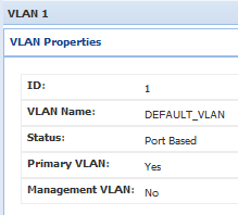
Perhaps, the "Primary VLAN" property causes ports UNTAGGED in VLAN 1 to act differently? Perhaps ports in the Primary VLAN also pass tagged VLAN packets?
I'd just have to experiment...
Hey, thanks a bunch for this "data trap" post! It's been very helpful.
-
@kevinrice My Aruba s2500 supports 'port mirroring'. This simply does a layer 2 copy of all packets to the mirror target port. Does yours have that option?
-
@andyrh said in Creating a "data tap":
@kevinrice My Aruba s2500 supports 'port mirroring'. This simply does a layer 2 copy of all packets to the mirror target port. Does yours have that option?
Yes...I think. The CLI commands used were:
Aruba2930F# conf t Aruba2930F(config)# mirror 1 port 1 Aruba2930F(config)# interface 2 monitor all both mirror 1 Aruba2930F(config)# -
@kevinrice said in Creating a "data tap":
First of all, I need to correct my terrible terminology, above. I actually "untagged" the ports on VLAN 4001 --- in HP parlance, "untagged" means inbound untagged traffic should be placed on the assigned VLAN (and the switch adds a tag internally). Outbound traffic has VLAN tags removed and becomes untagged traffic again as it exits an "untagged" port (or stays tagged if it exits a TAGGED port).
Again, I don't know anything about your switch. However I just connected my data tap between my main switch and access point. I use VLAN3 for the guest WiFi and I can see the tagged frames for it, as expected.
On my home network I have a Cisco managed switch. So, I have pfsense, my AP and the relevant switch ports configured for VLAN3. I also have 1 port I used for mirroring. When I mirror the port used for my AP or pfsense, I can see the VLAN tags. There aren't any VLAN tags on any other port.
The port you use for mirroring cannot have tagged VLANs. It must be able to pass everything.
-
@jknott Thanks for all the posts. I may give it another try in the home lab next week. I'm starting a 72-hour work shift this morning. I'll be home Tuesday!
-
 J JKnott referenced this topic on
-
J JKnott referenced this topic on
-
J JKnott referenced this topic on
-
J JKnott referenced this topic on
-
J JKnott referenced this topic on
-
J JKnott referenced this topic on
-
J JKnott referenced this topic on
-
J JKnott referenced this topic on
-
J JKnott referenced this topic on
-
J JKnott referenced this topic on
-
J JKnott referenced this topic on
-
A ahxcjay referenced this topic on
-
J JKnott referenced this topic on
-
H Havor referenced this topic on
-
J JKnott referenced this topic on
-
J JKnott referenced this topic on
-
J JKnott referenced this topic on
-
J JKnott referenced this topic on
-
J JKnott referenced this topic