GPS receiver advice for NTP
-
I have been searching the forum and other sites to obtain a very accurate/precise time keeper for my network. I am thinking of using a USGlobalSat MR-350P-S4, which uses the SiRF Star IV chipset (Amazon for $52.84). I was thinking of cutting off the PS/2 connector and use a small DB9 break-out board to connect the wires to their appropriate DB9 pins.
Upon looking at the datasheet for the USGlobalSat MR-350P-S4, I'll connect the black wire to DB9-pin 5, yellow wire to DB9-pin 9, white wire to DB9-pin 2 and the green wire to DB9-pin 3. I have a collection of AC/DC wall-warts, so I'm sure I already have a 5-6VDC power supply. I believe I will need to connect the positive wire of the power adapter to the red wire and join the ground wife of the power adapter to the black wire and pin 5 of the DB9 connector, correct? Now, the wire that comes with this GPS receiver is just under 15 feet. That may or may not be long enough to get from my roof to my pfSense machine, which was built using a Jetway NF9HG-2930 motherboard. If it is too short, it will be by only a few feet… would there be a problem using a DB9 serial extension cable? My plan is to plug it into the DB9 connector on the back panel of my pfSense machine, which I believe should be "cuau0". From the Services>NTP>Serial GPS tab, I believe I should set the GPS unit to SiRF, Serial Port to "cuau0", Baud will be left at 4800, and NMEA setences left at "all". Is there any reason to make any other changes on this tab?
I list all this to make sure I'm not overlooking something and if I screwed up, someone will hopefully point out where I screwed up. I have just purchased the GPS receiver and DB9 breakout board and hoping to do the install this next Monday. I am just hoping everything works the way I expect.
-
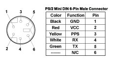
Personally I'd solder the PC and power cables to a female 6 pin mini DIN line socket, so that you don't need to cut off the factory fitted plug.
The yellow PPS wire goes to pin 1 (DCD), not pin 9 (RI).
The data sheet doesn't say whether the RX and TX pins are named using DTE or DCE conventions. If you have an oscilloscope, the pin where you see pulse trains goes to pin 2 and the other one goes to pin 3. If you don't have an oscilloscope, I'd start by trying the other way round to what you suggest - I think it most likely that the GPS sends on the green wire, which means that goes to the receive pin (pin 2) on the PC. It is almost certain you will cause no damage if you wire the RX and TX pins up the wrong way round - it just won't work.
If I'm correct over all this, you should be connecting:
GPS pin 1 (black) to serial pin 5 and power 0V
GPS pin 2 (red) to power +5V
GPS pin 3 (yellow) to serial pin 1
GPS pin 4 (white) to serial pin 3
GPS pin 5 (green) to serial pin 2You want to run the GPS in NMEA mode, not SiRF binary mode.
I only have experience of setting Garmin GPS 18x for lowest jitter, but the likelihood is that jitter will be reduced by minimising the workload on the GPS. This means you don't want the GPS to emit sentences that are not useful in a timing application. I'd set the GPS to emit GGA (which gives time, fix validity and number of satellites used in the solution) and ZDA (which gives time and date) and turn everything else off.
I would set the bit rate higher than 4800, as that increases the proportion of each second when the GPS is not emitting serial data. I'd try 19200. The chances are that 38400 and maybe even 57600 will be stable, though it's impossible to be certain.
The only unanswered question is the pulse length of the PPS signal. Some GPSes have a very short pulse length (of the order of 1ms) which might fail to work reliably with ntp. Unless you can get data from the manufacturer or find some information online, it's either a case of timing it yourself with an oscilloscope or seeing whether it works reliably.
-
Thanks for your info David. I looked again at the datasheet for the receiver and it didn't specify DTE or DCE but I also looked at the specifics for their own RS232 cable…

Interesting to see that the ONLY connections they are making to the DB9 is the white TX wire is going to DB9 pin 2 and the green RX wire is going to pin 3, so apparently I at least got that part of it correct. Their particular cable does not connect up the PPS wire for some reason. Thanks for clarifying PPS goes to pin 1 (DCD)… in my research, I saw in different projects, some used RI for PPS while others used DCD.
Below, as you can planely see is the setup page:

Under the GPS section, it says
Note: Default is the configuration of pfSense 2.1 and earlier (not recommended). Select Generic if your GPS is not listed.)
Note: The perdefined configurations assume your GPS has already been set to NMEA mode.As I am running the latest release of pfSense, 2.24, it says not to leave it as default. It also says to choose "Generic" if my GPS is not listed. Here is the list:
 I presume that since the chipset is SiRF, that is what I select. I believe that is still NMEA, just SiRF to be specific; unless pfSense wants to do something different with it, as it is an option.
When it comes to the baud rate, it says the default is 4800 for NMEA, that is why I was thinking of leaving that as is, but if there is no harm to increase the rate I can try that.
When it comes to NMEA sentences, do I need all the sentences? Should I only select certain sentences? Why do I have so many options?
When it comes to pulse length, the datasheet says: "1 uS(microsecond) pulse every second at 2.85v with 3D GPS Fix"
Again, I am definitely a newbie when it comes to GPS signals, NTP and clock precision… I'm just trying to learn and take advantage of features as I learn. At the moment, I don't think I have a true NEED for my timing to be perfect, but I think it would be cool to know it is.
-
Just select SIRF and accept all the values on the page below it.
-
I have abandoned the idea of using the DB9 breakout board like originally planned. I have now taken a new plan on how to connect everything and I hope it all works. I purchased a really small project box and will drill 3 holes in it. I have taken an old PS/2 extension cable and an old RS232 DB9 extension cable and cut off the male ends (no gender jokes intended ;D ). I have stripped the shielding on each of the cables. Thankfully, each wire is a different color on both cables.

Since I know that for the GPS device ground is on pin 1 and 5VDC is on pin 2, I will put a DC barrel jack in my little project with the orange wire going to ground and red wire going to the center pin. The other applicable wires, I will use small IDC 2-wire button splicers to join wires between the PS/2-type connector to the DB9 wire. For the PPS, the GPS unit will be on pin 3 of the PS/2 and this will go to pin 1 on DB9, so I'll splice PS/2-yellow to DB9-black. For RX, the GPS unit uses pin 4 and this will go to pin 2 on the DB9, so I'll splice PS/2-brown to DB9-brown. For TX, the GPS uses pin 5 which should go to pin 3 on the DB9, so PS/2-green will be spliced with DB9-red. The cut ends with all the splices will be inside the little project box, so it will have two cables coming out of it and one DC barrel jack in it. I will then plug the GPS unit's male PS/2-type connector into the female PS/2-type connector of the project box. The DB9 female connector will then plug into the serial port on the back of my pfSense device. Finally, I'll plug a 5VDC wall wart into the DC barrel jack. All of this is fairly inexpensive and mostly from parts I already had in my collection from previous projects or devices.
I am posting this first to make sure I haven't screwed up with anything and for other's sake if they are trying to do something similar if I'm successful and as a reference to myself if I am trying to remember what I did.
-
This post is deleted!
