pfSense and IPSEC lan to lan: a big doubt about the correct implementation
-
Trying to start the ipsec tunnel from the pfsense 10.99.0.2 on the left side (site A) to pfsense 3.3.3.3 and analysing the traffic with Wireshark I see that
without changing the identifier:
8003 2022-11-30 02:11:35.758047 3.3.3.1 3.3.3.3 ISAKMP 506 IKE_SA_INIT MID=00 Initiator Request
8004 2022-11-30 02:11:35.763770 3.3.3.1 3.3.3.3 ISAKMP 78 IKE_SA_INIT MID=00 Responder Responsechanging the identifier:
8003 2022-11-30 02:14:35.283948 3.3.3.1 3.3.3.3 ISAKMP 506 IKE_SA_INIT MID=00 Initiator Request
8004 2022-11-30 02:14:35.283970 3.3.3.1 3.3.3.3 ISAKMP 78 IKE_SA_INIT MID=00 Responder ResponseSince the IP 10.99.0.2 is behind NAT, I should use the "IP address" identifier, ok.
But why should I use the 3.3.3.3 and not the 1.1.1.1? This question is because 10.99.0.2 is behind the public IP 1.1.1.1 and because I read:"IP Address
A specific static and manually-entered IP address to be used as the identifier. One potential use for this is when the firewall is behind NAT where the real external IP address could be used in this field."Was it a typo?
Anyway, as you can see, in the schema there are two routers and they are running with NAT enabled...
Is the "IP address" identifier enough to bypass the NAT effects of both of them?Thank you.
-
Sorry, yes that was a typo. The IP address used for the identifier should be the local public IP. So the pfSense at site A should indeed use 1.1.1.1.
I was assuming that 3.3.3.3/25 is a public subnet here so that side is not behind NAT. Is that not the case?
Steve
-
Good morning Steve, in order to simplify your analysis I created a new GNS3 Lab simulating the real scenario.
In this schema you can see all the IP addresses (only two of them are public IPs) and all the involved instances .
Below you can find some important info:
- 10.99.0.0/24 is the transport network that you suggested to use;
- 192.168.118.0/24 and 192.168.120/24 are the LAN I would like to "join" using IPSEC VPN;
- you can ignore the dotted links since they are here only for management purposes;
- RouterA can ping RouterB and they have NAT enabled;
- pfsenseA can ping RouterB public IP;
- pfsenseB can ping RouterA public IP;
- in addition to the basic/standard IPSEC configuration, I set the identifiers as you suggested (on pfsenseA ipaddress id 192.168.122.230, on pfsenseB ipaddress id 192.168.122.205);
- when I try to start IPSEC tunnel from pfsenseA, no connection starts

- the IPSEC logs say that:

- this is what I see if I check the traffic using Wireshark on the WAN interface of routerB:
9 2022-11-30 14:43:44.663606 192.168.122.230 192.168.122.205 ISAKMP 506 IKE_SA_INIT MID=00 Initiator Request
10 2022-11-30 14:43:44.665168 192.168.122.205 192.168.122.230 ICMP 534 Destination unreachable (Port unreachable)and nothing else related to this kind of connection.
- No relevant traffic seems to be passed from RouterB to WAN interface of pfsenseB
It seems that the IPSEC traffic and port are not "passed" from RouterB to WAN interface of pfsenseB. I read a lot of things about IPSEC behind NAT, someone says that we should activate a port forwarding on the routers ( 192.168.122.230:500 > 10.99.0.2:500, 192.168.122.205:500 > 10.55.0.11:500) other people talks about NAT-T but I didn't understand when and where I should activated it. Someone says that also Peer identifier should be changed...
Could you please help me again to understand ?
Many thanks in advance for you patience,
Mauro -
Do you have a new diagram showing those subnets?
So 3.3.3.3/25 is not a public subnet?
If both sides are behind NAT you will need to forward the IPSec traffic through one of the external routers to pfSense in order to bring up the tunnel reliably. Without that you rely on both ends opening outbound states at the same time that match the incoming traffic which may or may not happen.
Steve
-
-
Ok, so is 10.55.0.0/24 at site B a public routed subnet there?
If not both sides are behind NAT and you will need to forward traffic in router A and/or B to establish the connection.
-
In your original diagram you have a /30 transport subnet bewteen the ISP and Router B and then a /25 behind Router B which looks like it would be a public subnet?
-
@stephenw10 said in pfSense and IPSEC lan to lan: a big doubt about the correct implementation:
Ok, so is 10.55.0.0/24 at site B a public routed subnet there?
Yes, it is :) in the real scenario it is a public routed subnet.
-
Ok, then you need to replicate that. pfSense B has a public IP and the tunnel should be using that directly, not the router B address.
-
I also note that the pfSense IP is 3.3.3.2 and you appear to have used 3.3.3.3 as the remote host IP at site A. Is that a typo?
-
@stephenw10 yes, it was a typo, but, please, refer only to the last schema I attached here :)
-
@stephenw10 mmmmmc ok, you are right. thank you.
Do you know how can I do it in GNS3 first?
Thanks,
Mauro -
Well you would need to add 10.55.0.0/24 as a static route via Router B. Then in router B configure it not to NAT that traffic.
Or just remove router B entirely and put 192.168.122.205 on pfSense B directly.
-
@stephenw10 many thanks again for your patience.
Now the schema is the following one:

And it seems that something is working (thank you Steve).

At this moment, there is no traffic forward rule on RouterA.
The IPSEC tunnel is started from pfsenseA (I only added the identifier as you suggested)Now the last step before closing this case.
PC1 and PC2 are not able to ping each other. IPSEC firewall rules allow any traffic to any hosts, but there is this last problem.On every pfsense interfaces there is a single rule that allows any traffic to any hosts and ports.
What do you think I'm missing ?
-
Ok so the tunnel is up at P1 and P2. The subnets it's carrying look correct.
The traffic counters show 0 packets in or out. Does it show that at both ends?
I would guess that you are missing the route on Router A to 192.168.120.0/24 via pfSense A.
Client at site B should still be able to send though and that should match the policy and be sent over the tunnel.
-
Unfortunately, the route on router A has been already set.
-
Ok, then check both ends, do the traffic counters still show as 0 after trying to ping in both directions?
How exactly are you running that ping?
Do you see anything blocked in the firewall logs?
-
@stephenw10 said in pfSense and IPSEC lan to lan: a big doubt about the correct implementation:
Ok, then check both ends, do the traffic counters still show as 0 after trying to ping in both directions?
yes, 0 stats on both the ends
How exactly are you running that ping?
I'm executing ping from the VPCS on the left of the schema (192.168.118.10) to the VPCS on the right (192.168.120.10) and viceversa
Do you see anything blocked in the firewall logs?
During the last attempts, it seems that nothing have been blocked but I will check again soon
-
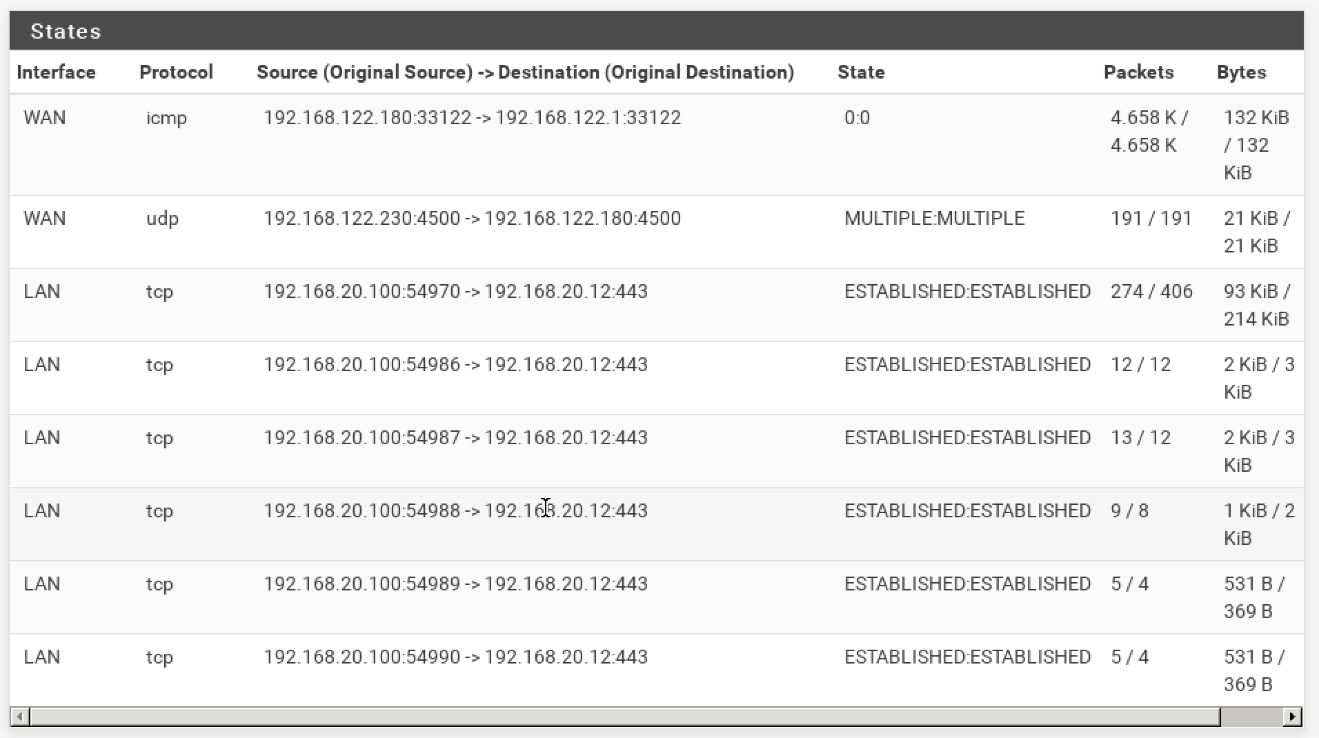
The other thing to check is the state table in Diag > States. You should see states on the LAN and IPSec interfaces for the pings on each side.
At site B there is really nothing to stop IPSec at least sending pings from 192.168.120.10 to 192.168.118.10 over the tunnel.
At site A there are other things that could be preventing it. -
Ok, these are the states for the pfsenseA

and these are the states for the pfsenseB
Question: on the Router A I created a route 192.168.120.0/24 > 10.99.0.2.
Do I need to create a route rule also on pfsense A ? something like that: 192.168.118.0/24 > 10.99.0.1?
