[As Good As Solved!] Watchguard Firebox Arm/Disarm LED
-
Haha! Victory is mine! ;D
After way too much time trying this has been quite an education but…
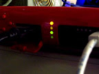
Very long story short. On the X-Core-E box (an X750E) that I'm using for testing the arm/disarm led is driven by a pair of gpio pins on the ICH6 Southbridge chip. Specifically:
GPIO27 = Red/Disarmed LED
GPIO28 = Green/Armed LED
The led itself is a bi-colour led (obviously) but it is the two pin type so no orange is possible. :(
The leds can be flashed by setting the appropriate 'blink' register in the ich6.It seemed incredibly hard to pin down all the information to get this working and even now I'm pretty sure I was lucky.
I'm not yet sure if any of this applies to other Fireboxes but it will be fine on all the Xe type as they all have the same hardware.
The GPIO pins are accessed by writing to the appropriate IO space. That is defined as GPIObase address + offset to gpio level register. I'm not sure how you're supposed to be able to find the base address so I guessed based on other documentation. It seems to be usually at 0x480and it is in the firebox.
The bios sets up the correct registers to enable the GPIO pins and set them as outputs so all you have to do is change the values:
GP27 equates to 0x48f, bit3
GP28 equates to 0x48f, bit4
You need to set one or other to 1 as if both are high the led has +v on both ends.
I wrote a little program, mostly by copy and pasting, here.
I don't seem to have done any damage to my box setting any of the bits at 0x48f so I think it's fairly safe however the original value was 0x0B so in order to change the LED to green:[2.0-BETA5][root@pfSense.localdomain]/root(50): ./writeio 0x48f 0x13 Setting 48f to 13And back to red:
[2.0-BETA5][root@pfSense.localdomain]/root(49): ./writeio 0x48f 0x0b
Setting 48f to b
And to make it green flash:
[2.0-BETA5][root@pfSense.localdomain]/root(51): ./writeio 0x49b 0x10
Setting 49b to 10
Anf to make red flash:
[2.0-BETA5][root@pfSense.localdomain]/root(54): ./writeio 0x49b 0x08
Setting 49b to 8
To stop flashing:
[2.0-BETA5][root@pfSense.localdomain]/root(53): ./writeio 0x49b 0x00
Setting 49b to 0
Note that if you set either red or green to flash then it will appear that both red and green are flashing as the steady signal will be flashed by a switching one at the other end of the led.
The original Watchguard firmware has two flashing speeds but I've not found anyway to do that at a hardware level.
The program has no error checking or sanity checking so it's likely you could cause all kinds of damage by entering random figures! :P
Let me know if this works for you.Steve
Edit: I've not found how the expansion led is controlled yet, possibly some other means all together.
Edit2: Perhaps only partial victory is mine. ::) The southbridge in the X-peak hardware is ICH5 which has the same set of GPIOs in the same memory location however they do not control the arm/disarm led on that box. I'm forced to conclude that all the boxes are different and will require more study. :(
-
wow you've made a huge step! very awesome!
-
Very interesting indeed, I'm going to give this a shot this weekend.
-
Having tried this on my X6000 (X-peak) box it definitely doesn't work. Having said that it didn't do any harm either so if you want to try it on any of the Fireboxes I think it's safe enough.
I think this information is only relevant to the Xe (X550e, X750e etc) boxes.
You'd have thought that Watchguard would have wanted a consistent interface across their models but that doesn't appear to be the case.Steve
-
I have a much nicer newer program here.
This does fan speed query and setting as well as led changing.[2.0-BETA5][root@pfSense.localdomain]/var/tmp(54): ./WGXe WGXe can accept two arguments: -f (fan) will return the current fan speed or if followed by a number in hex, 00-FF, will set it. -l (led) will set the arm/disarm to the second argument: red, green, red_flash, green_flash, offAgain this is, currently, only relevant to the Xe Firebox.
Steve
-
That's still very promising.
You could write a little GUI for it (feel free to look at/steal the code from the blinkled files in the packages repo) and we could put up a package for controlling the LED there. Having it work for one model is better than for none. If nothing else you could just have a setting for which color to make the LED at bootup, and then when the package sync's it could set the LED color.
You could even make a little dashboard widget (they're super simple to write) that shows the fan speed.
-
Thanks for that. It makes me smile every time seeing that LED turn green. ;D
At the moment I have a bash script in /usr/local/etc/rc.d that sets the fan speed changes the led colour.
Unfortunately the speed returned by the -f switch is only the current setting not the actual speed so I think a dashboard widget might be a bit boring! This is due to the fans only being three wire causing the PWM speed control to confuse the speed sensor output.The Firebox LCD 'package' hasn't made it into a real package yet. Perhaps we could create a single package for Firebox users? I'm not sure how Watchguard might feel about that though? ::)
Steve
-
Yeah there could be a package, either for that model specifically or for them in general. Though a more general package may be a little tougher to get right if you have to pick and choose the model as well as the features supported by that model.
…and as far as what watchguard thinks, it's a community-contributed package. Though even if it wasn't, there probably isn't much they can do. You could just rename it if they whine about the use of their name. It could just be a SmatchBlard BireFox package ;-)
-
This is great, hope both the firebox (x core) lcd and this new (Xe) LED / fanspeed make it into packages.
Once again, neat work stephenw10! -
Some more progress. :)
I have found the control for the arm/disarm led on the X-Peak box. It's connected to the gpios on the ICH5 southbridge chip, like the Xe, however on the 6300ESB in the x-peak it's controlled by gpio40 (red) and gpio41 (green). The 6300ESB has four special gpios capable of driving leds directly (40-43) which is why I think they are using these instead of the same as the Xe. Anyway these are controlled by the 0x4B9 register on bits 0 and 1. E.g. for red:[2.0-BETA4][root@pfSense.localdomain]/var/tmp(62): ./writeio 0x4b9 0d Setting 4b9 to dAnd for green:
[2.0-BETA4][root@pfSense.localdomain]/var/tmp(63): ./writeio 0x4b9 0e
Setting 4b9 to e
Unfortunately there is no 'built in' flashing capability for these gpios. :(
I think watchguard had software flashing as they had fast and slow ability as well.This new result leads me to believe that the X-core is almost certainly on a southbridge gpio also but I don't have an X-core to hand to test (yet!).
Steve
Edit: Here is a newer version of the program that can control both the Xe and X-Peak boxes.
-
Stephenw10, I have two fireboxes that once were a x700 and an x500, only one of which is in 'production' at any given moment.
Is there something I can help test for you? -
Yep. It's a pretty simple test procedure.
I'm not sure what the southbridge is in the X-core. I had in my mind that it's the ICH0 but now I can't find where I might have read that. Anyway first check your bootup dmesg for the chip. I'm pretty sure it's a 82801ab in which case get the data sheet here. Now the idea is to probe the register addresses and check the result against the defaults listed on the data sheet. Look for what has been changed. On that data sheet the section you are looking for is 8.10.1 GPIO Register I/O Address Map.
Download the two programs I wrote,readio and writeio, from here.
Copy them to your box and change the permissions to 0755 so you can run them.
Then read the address with readio followed by a hex value.
The base address of the gpio is almost certainly 0x480 (but might not be!) so to read the first register:[2.0-BETA5][root@pfSense.localdomain]/root(22): ./readio 0x480 Reading 480 :81Except it won't be 81 on your box.
You need to read;
0x480-0x483. GPIO use select
0x484-0x487. GPIO input or output select
0x48c-0x48f. Actual GPIO values.
The numbers you'll get come out in reverse order, 0x480 is the least significant byte of that register.
Although you start out with 32 possible gpios you'll see that only a few are contenders. They need to be set as gpio in use select (1) and set as outout in I/O select (0).
Then use writeio (register, value) to change the numbers and see if the led goes out.
Write everything down!Steve
Edit: And if none of that works there's a second set of registers as I found out for the X-peak.
-
Thanks for all that info, very interesting stuff!
I copied your read and write programs to /etc/rd.d, chmod 0755 and ran the 0x48* commands.
Every answer is the same; Reading 480 :ff.
I'm probably doing something wrong. -
Hmm, Ok.
You issued each inquiry separately like so:[2.0-BETA5][root@pfSense.localdomain]/root(5): ./readio 0x480 Reading 480 :81 [2.0-BETA5][root@pfSense.localdomain]/root(6): ./readio 0x481 Reading 481 :31 [2.0-BETA5][root@pfSense.localdomain]/root(7): ./readio 0x482 Reading 482 :a8Also ff is not what I'd expect from 0x480, default value are 60 or E0 for 82801AA/AB. Is that the chip that's fitted?
It could be that they changed the base address or that the default base address is different.Steve
-
You issued each inquiry separately like so:
[2.0-BETA5][root@pfSense.localdomain]/root(5): ./readio 0x480
Reading 480 :81
Also ff is not what I'd expect from 0x480, default value are 60 or E0 for 82801AA/AB. Is that the chip that's fitted?
It could be that they changed the base address or that the default base address is different.Yes, I ran each command separately, on both the x500 and x700 (some small differences between the two machines despite being supposedly the same), and every answer was the same, for instance:
[2.0-BETA5][admin@firebox1.domain]/etc/rc.d(6): ./readio 0x482
Reading 482 :ff
And on the other machine:
[2.0-BETA5][admin@firebox2.domain]/etc/rc.d(8): ./readio 0x485
Reading 485 :ff
Also, no matter what command I issue, the answer is always the same:
[2.0-BETA5][admin@firebox1.domain]/etc/rc.d(11): ./readio 0x2488
Reading 2488 :ff
I'm not sure what chip is inside, is there a way to find out other than opening up the case?
edit: copy paste errors
-
Ok, well that implies we are looking in completely the wrong place!
You should be able to see the chip number in dmesg.[2.0-BETA5][root@pfSense.localdomain]/root(6): dmesg|grep ICH uhci0: <intel 82801fb="" fr="" fw="" frw="" (ich6)="" usb="" controller="" usb-a="">port 0xeb00-0xeb1f irq 23 at device 29.0 on pci0 usbus0: <intel 82801fb="" fr="" fw="" frw="" (ich6)="" usb="" controller="" usb-a="">on uhci0 uhci1: <intel 82801fb="" fr="" fw="" frw="" (ich6)="" usb="" controller="" usb-b="">port 0xed00-0xed1f irq 19 at device 29.1 on pci0 usbus1: <intel 82801fb="" fr="" fw="" frw="" (ich6)="" usb="" controller="" usb-b="">on uhci1 uhci2: <intel 82801fb="" fr="" fw="" frw="" (ich6)="" usb="" controller="" usb-c="">port 0xe800-0xe81f irq 18 at device 29.2 on pci0 usbus2: <intel 82801fb="" fr="" fw="" frw="" (ich6)="" usb="" controller="" usb-c="">on uhci2 uhci3: <intel 82801fb="" fr="" fw="" frw="" (ich6)="" usb="" controller="" usb-d="">port 0xe900-0xe91f irq 16 at device 29.3 on pci0 usbus3: <intel 82801fb="" fr="" fw="" frw="" (ich6)="" usb="" controller="" usb-d="">on uhci3 ehci0: <intel 82801fb="" (ich6)="" usb="" 2.0="" controller="">mem 0xd05c0000-0xd05c03ff irq 23 at device 29.7 on pci0 usbus4: <intel 82801fb="" (ich6)="" usb="" 2.0="" controller="">on ehci0 atapci0: <intel ich6="" udma100="" controller="">port 0x1f0-0x1f7,0x3f6,0x170-0x177,0x376,0xf000-0xf00f at device 31.1 on pci0</intel></intel></intel></intel></intel></intel></intel></intel></intel></intel></intel>If isn't an ich device you might try grepping for Intel or something!
Steve
-
Allright, I ran dmesg on firebox1 (previously x500) and got the following:
[2.0-BETA5][admin@firebox1.domain]/root(1): dmesg|grep ICHatapci0: <intel ich2="" udma100="" controller="">port 0x1f0-0x1f7,0x3f6,0x170-0x177,0x376,0xff00-0xff0f at device 31.1 on pci0
atapci0: <intel ich2="" udma100="" controller="">port 0x1f0-0x1f7,0x3f6,0x170-0x177,0x376,0xff00-0xff0f at device 31.1 on pci0</intel></intel>
Then I grepped for Intel, which got me the following:
[2.0-BETA5][admin@firebox1.domain]/root(2): dmesg | grep Intel
CPU: Intel(R) Celeron(TM) CPU                1200MHz (1202.73-MHz 686-class CPU)
  Origin = "GenuineIntel"  Id = 0x6b4  Family = 6  Model = b  Stepping = 4
pcib0: <intel 82815="" (i815="" gmch)="" host="" to="" hub="" bridge="">pcibus 0 on motherboard
atapci0: <intel ich2="" udma100="" controller="">port 0x1f0-0x1f7,0x3f6,0x170-0x177,0x376,0xff00-0xff0f at device 31.1 on pci0
CPU: Intel(R) Celeron(TM) CPU                1200MHz (1202.73-MHz 686-class CPU)
  Origin = "GenuineIntel"  Id = 0x6b4  Family = 6  Model = b  Stepping = 4
pcib0: <intel 82815="" (i815="" gmch)="" host="" to="" hub="" bridge="">pcibus 0 on motherboard
atapci0: <intel ich2="" udma100="" controller="">port 0x1f0-0x1f7,0x3f6,0x170-0x177,0x376,0xff00-0xff0f at device 31.1 on pci0</intel></intel></intel></intel>
And I still don't see what we were looking for so I ran dmesg without grep, which resulted in a rather odd output as you can see here:
[2.0-BETA5][admin@firebox1.virtualflo.com]/root(3): dmesg
re2: link state changed to DOWN
re3: link state changed to DOWN
re4: link state changed to DOWN
re5: link state changed to DOWN
pid 6206 (nice), uid 0: exited on signal 11 (core dumped)
pid 6446 (pfctl), uid 0: exited on signal 11 (core dumped)
pflog0: promiscuous mode disabled
Waiting (max 60 seconds) for system process `vnlru' to stop...done
Waiting (max 60 seconds) for system process `bufdaemon' to stop...done
Waiting (max 60 seconds) for system process `syncer' to stop...
Syncing disks, vnodes remaining...0 0 done
All buffers synced.
Uptime: 13h38m4s
Rebooting...
Copyright (c) 1992-2010 The FreeBSD Project.
Copyright (c) 1979, 1980, 1983, 1986, 1988, 1989, 1991, 1992, 1993, 1994
	The Regents of the University of California. All rights reserved.
FreeBSD is a registered trademark of The FreeBSD Foundation.
FreeBSD 8.1-RELEASE-p2 #1: Tue Feb  8 17:40:15 EST 2011
    sullrich@FreeBSD_8.0_pfSense_2.0-snaps.pfsense.org:/usr/obj.pfSense/usr/pfSensesrc/src/sys/pfSense_wrap.8.i386 i386
Timecounter "i8254" frequency 1193182 Hz quality 0
CPU: Intel(R) Celeron(TM) CPU                1200MHz (1202.73-MHz 686-class CPU)
  Origin = "GenuineIntel"  Id = 0x6b4  Family = 6  Model = b  Stepping = 4
  Features=0x383f9ff <fpu,vme,de,pse,tsc,msr,pae,mce,cx8,sep,mtrr,pge,mca,cmov,pat,pse36,mmx,fxsr,sse>real memory  = 268435456 (256 MB)
avail memory = 243433472 (232 MB)
wlan: mac acl policy registered
ipw_bss: You need to read the LICENSE file in /usr/share/doc/legal/intel_ipw/.
ipw_bss: If you agree with the license, set legal.intel_ipw.license_ack=1 in /boot/loader.conf.
module_register_init: MOD_LOAD (ipw_bss_fw, 0xc0700bd0, 0) error 1
ipw_ibss: You need to read the LICENSE file in /usr/share/doc/legal/intel_ipw/.
ipw_ibss: If you agree with the license, set legal.intel_ipw.license_ack=1 in /boot/loader.conf.
module_register_init: MOD_LOAD (ipw_ibss_fw, 0xc0700c70, 0) error 1
wpi: You need to read the LICENSE file in /usr/share/doc/legal/intel_wpi/.
wpi: If you agree with the license, set legal.intel_wpi.license_ack=1 in /boot/loader.conf.
module_register_init: MOD_LOAD (wpi_fw, 0xc0873920, 0) error 1
ipw_monitor: You need to read the LICENSE file in /usr/share/doc/legal/intel_ipw/.
ipw_monitor: If you agree with the license, set legal.intel_ipw.license_ack=1 in /boot/loader.conf.
module_register_init: MOD_LOAD (ipw_monitor_fw, 0xc0700d10, 0) error 1
ACPI Error: A valid RSDP was not found (20100331/tbxfroot-309)
ACPI: Table initialisation failed: AE_NOT_FOUND
ACPI: Try disabling either ACPI or apic support.
cryptosoft0: <software crypto=""> on motherboard
padlock0: No ACE support.
pcib0: <intel 82815="" (i815="" gmch)="" host="" to="" hub="" bridge=""> pcibus 0 on motherboard
pir0: <pci 11="" interrupt="" routing="" table:="" entries=""> on motherboard
$PIR: Using invalid BIOS IRQ 9 from 2.13.INTA for link 0x63
pci0: <pci bus=""> on pcib0
pcib1: <pcibios pci-pci="" bridge=""> at device 30.0 on pci0
pci2: <pci bus=""> on pcib1
safe0 mem 0xefbfe000-0xefbfffff irq 3 at device 6.0 on pci2
safe0: [ITHREAD]
safe0: SafeNet SafeXcel-1141 rng des/3des aes md5 sha1 null
re0: <realtek 10="" 8139c+="" 100basetx=""> port 0xd500-0xd5ff mem 0xefefa000-0xefefa1ff irq 10 at device 9.0 on pci2
re0: Chip rev. 0x74800000
re0: MAC rev. 0x00000000
miibus0: <mii bus=""> on re0
rlphy0: <realtek internal="" media="" interface=""> PHY 0 on miibus0
rlphy0:  10baseT, 10baseT-FDX, 100baseTX, 100baseTX-FDX, auto
re0: [FILTER]
re1: <realtek 10="" 8139c+="" 100basetx=""> port 0xd600-0xd6ff mem 0xefefb000-0xefefb1ff irq 5 at device 10.0 on pci2
re1: Chip rev. 0x74800000
re1: MAC rev. 0x00000000
miibus1: <mii bus=""> on re1
rlphy1: <realtek internal="" media="" interface=""> PHY 0 on miibus1
rlphy1:  10baseT, 10baseT-FDX, 100baseTX, 100baseTX-FDX, auto
re1: [FILTER]
re2: <realtek 10="" 8139c+="" 100basetx=""> port 0xd900-0xd9ff mem 0xefefc000-0xefefc1ff irq 11 at device 11.0 on pci2
re2: Chip rev. 0x74800000
re2: MAC rev. 0x00000000
miibus2: <mii bus=""> on re2
rlphy2: <realtek internal="" media="" interface=""> PHY 0 on miibus2
rlphy2:  10baseT, 10baseT-FDX, 100baseTX, 100baseTX-FDX, auto
re2: [FILTER]
re3: <realtek 10="" 8139c+="" 100basetx=""> port 0xda00-0xdaff mem 0xefefd000-0xefefd1ff irq 12 at device 12.0 on pci2
re3: Chip rev. 0x74800000
re3: MAC rev. 0x00000000
miibus3: <mii bus=""> on re3
rlphy3: <realtek internal="" media="" interface=""> PHY 0 on miibus3
rlphy3:  10baseT, 10baseT-FDX, 100baseTX, 100baseTX-FDX, auto
re3: [FILTER]
re4: <realtek 10="" 8139c+="" 100basetx=""> port 0xdd00-0xddff mem 0xefefe000-0xefefe1ff irq 9 at device 13.0 on pci2
re4: Chip rev. 0x74800000
re4: MAC rev. 0x00000000
miibus4: <mii bus=""> on re4
rlphy4: <realtek internal="" media="" interface=""> PHY 0 on miibus4
rlphy4:  10baseT, 10baseT-FDX, 100baseTX, 100baseTX-FDX, auto
re4: [FILTER]
re5: <realtek 10="" 8139c+="" 100basetx=""> port 0xde00-0xdeff mem 0xefeff000-0xefeff1ff irq 6 at device 14.0 on pci2
re5: Chip rev. 0x74800000
re5: MAC rev. 0x00000000
miibus5: <mii bus=""> on re5
rlphy5: <realtek internal="" media="" interface=""> PHY 0 on miibus5
rlphy5:  10baseT, 10baseT-FDX, 100baseTX, 100baseTX-FDX, auto
re5: [FILTER]
isab0: <pci-isa bridge=""> at device 31.0 on pci0
isa0: <isa bus=""> on isab0
atapci0: <intel ich2="" udma100="" controller=""> port 0x1f0-0x1f7,0x3f6,0x170-0x177,0x376,0xff00-0xff0f at device 31.1 on pci0
ata0: <ata 0="" channel=""> on atapci0
ata0: [ITHREAD]
ata1: <ata 1="" channel=""> on atapci0
ata1: [ITHREAD]
cpu0 on motherboard
unknown: <pnp0c01> can't assign resources (memory)
atrtc0: <at realtime="" clock=""> at port 0x70-0x71 irq 8 pnpid PNP0b00 on isa0
uart0: <16550 or compatible> at port 0x3f8-0x3ff irq 4 flags 0x10 pnpid PNP0501 on isa0
uart0: [FILTER]
uart0: console (9600,n,8,1)
ppc0: <ecp parallel="" printer="" port=""> at port 0x378-0x37f,0x778-0x77a irq 7 drq 3 pnpid PNP0401 on isa0
ppc0: Generic chipset (ECP/PS2/NIBBLE) in COMPATIBLE mode
ppc0: FIFO with 16/16/16 bytes threshold
ppc0: [ITHREAD]
ppbus0: <parallel port="" bus=""> on ppc0
ppi0: <parallel i="" o=""> on ppbus0
orm0: <isa option="" rom=""> at iomem 0xe0000-0xe0fff pnpid ORM0000 on isa0
unknown: <pnp0c01> can't assign resources (memory)
RTC BIOS diagnostic error 20 <config_unit>Timecounter "TSC" frequency 1202731522 Hz quality 800
Timecounters tick every 10.000 msec
IPsec: Initialized Security Association Processing.
ata1: DMA limited to UDMA33, controller found non-ATA66 cable
ad2: 5729MB <toshiba mk6014map="" n2.10="" a=""> at ata1-master UDMA33
GEOM: ad2s1: geometry does not match label (255h,63s != 15h,63s).
Trying to mount root from ufs:/dev/ad2s1a
pflog0: promiscuous mode enabled
ovpns1: link state changed to UP
re1: link state changed to UP
pid 7510 (rrdtool), uid 0: exited on signal 11 (core dumped)
re2: link state changed to DOWN
re3: link state changed to DOWN
re4: link state changed to DOWN
re5: link state changed to DOWN
pflog0: promiscuous mode disabled
Waiting (max 60 seconds) for system process `vnlru' to stop...done
Waiting (max 60 seconds) for system process `bufdaemon' to stop...done
Waiting (max 60 seconds) for system process `syncer' to stop...
Syncing disks, vnodes remaining...0 0 done
All buffers synced.
Uptime: 1d3h28m51s
Rebooting...
Copyright (c) 1992-2010 The FreeBSD Project.
Copyright (c) 1979, 1980, 1983, 1986, 1988, 1989, 1991, 1992, 1993, 1994
	The Regents of the University of California. All rights reserved.
FreeBSD is a registered trademark of The FreeBSD Foundation.
FreeBSD 8.1-RELEASE-p2 #1: Wed Feb  9 15:55:23 EST 2011
    sullrich@FreeBSD_8.0_pfSense_2.0-snaps.pfsense.org:/usr/obj.pfSense/usr/pfSensesrc/src/sys/pfSense_wrap.8.i386 i386
Timecounter "i8254" frequency 1193182 Hz quality 0
CPU: Intel(R) Celeron(TM) CPU                1200MHz (1202.73-MHz 686-class CPU)
  Origin = "GenuineIntel"  Id = 0x6b4  Family = 6  Model = b  Stepping = 4
  Features=0x383f9ff <fpu,vme,de,pse,tsc,msr,pae,mce,cx8,sep,mtrr,pge,mca,cmov,pat,pse36,mmx,fxsr,sse>real memory  = 268435456 (256 MB)
avail memory = 243433472 (232 MB)
wlan: mac acl policy registered
ipw_bss: You need to read the LICENSE file in /usr/share/doc/legal/intel_ipw/.
ipw_bss: If you agree with the license, set legal.intel_ipw.license_ack=1 in /boot/loader.conf.
module_register_init: MOD_LOAD (ipw_bss_fw, 0xc0700be0, 0) error 1
ipw_ibss: You need to read the LICENSE file in /usr/share/doc/legal/intel_ipw/.
ipw_ibss: If you agree with the license, set legal.intel_ipw.license_ack=1 in /boot/loader.conf.
module_register_init: MOD_LOAD (ipw_ibss_fw, 0xc0700c80, 0) error 1
wpi: You need to read the LICENSE file in /usr/share/doc/legal/intel_wpi/.
wpi: If you agree with the license, set legal.intel_wpi.license_ack=1 in /boot/loader.conf.
module_register_init: MOD_LOAD (wpi_fw, 0xc0873930, 0) error 1
ipw_monitor: You need to read the LICENSE file in /usr/share/doc/legal/intel_ipw/.
ipw_monitor: If you agree with the license, set legal.intel_ipw.license_ack=1 in /boot/loader.conf.
module_register_init: MOD_LOAD (ipw_monitor_fw, 0xc0700d20, 0) error 1
ACPI Error: A valid RSDP was not found (20100331/tbxfroot-309)
ACPI: Table initialisation failed: AE_NOT_FOUND
ACPI: Try disabling either ACPI or apic support.
cryptosoft0: <software crypto=""> on motherboard
padlock0: No ACE support.
pcib0: <intel 82815="" (i815="" gmch)="" host="" to="" hub="" bridge=""> pcibus 0 on motherboard
pir0: <pci 11="" interrupt="" routing="" table:="" entries=""> on motherboard
$PIR: Using invalid BIOS IRQ 9 from 2.13.INTA for link 0x63
pci0: <pci bus=""> on pcib0
pcib1: <pcibios pci-pci="" bridge=""> at device 30.0 on pci0
pci2: <pci bus=""> on pcib1
safe0 mem 0xefbfe000-0xefbfffff irq 3 at device 6.0 on pci2
safe0: [ITHREAD]
safe0: SafeNet SafeXcel-1141 rng des/3des aes md5 sha1 null
re0: <realtek 10="" 8139c+="" 100basetx=""> port 0xd500-0xd5ff mem 0xefefa000-0xefefa1ff irq 10 at device 9.0 on pci2
re0: Chip rev. 0x74800000
re0: MAC rev. 0x00000000
miibus0: <mii bus=""> on re0
rlphy0: <realtek internal="" media="" interface=""> PHY 0 on miibus0
rlphy0:  10baseT, 10baseT-FDX, 100baseTX, 100baseTX-FDX, auto
re0: [FILTER]
re1: <realtek 10="" 8139c+="" 100basetx=""> port 0xd600-0xd6ff mem 0xefefb000-0xefefb1ff irq 5 at device 10.0 on pci2
re1: Chip rev. 0x74800000
re1: MAC rev. 0x00000000
miibus1: <mii bus=""> on re1
rlphy1: <realtek internal="" media="" interface=""> PHY 0 on miibus1
rlphy1:  10baseT, 10baseT-FDX, 100baseTX, 100baseTX-FDX, auto
re1: [FILTER]
re2: <realtek 10="" 8139c+="" 100basetx=""> port 0xd900-0xd9ff mem 0xefefc000-0xefefc1ff irq 11 at device 11.0 on pci2
re2: Chip rev. 0x74800000
re2: MAC rev. 0x00000000
miibus2: <mii bus=""> on re2
rlphy2: <realtek internal="" media="" interface=""> PHY 0 on miibus2
rlphy2:  10baseT, 10baseT-FDX, 100baseTX, 100baseTX-FDX, auto
re2: [FILTER]
re3: <realtek 10="" 8139c+="" 100basetx=""> port 0xda00-0xdaff mem 0xefefd000-0xefefd1ff irq 12 at device 12.0 on pci2
re3: Chip rev. 0x74800000
re3: MAC rev. 0x00000000
miibus3: <mii bus=""> on re3
rlphy3: <realtek internal="" media="" interface=""> PHY 0 on miibus3
rlphy3:  10baseT, 10baseT-FDX, 100baseTX, 100baseTX-FDX, auto
re3: [FILTER]
re4: <realtek 10="" 8139c+="" 100basetx=""> port 0xdd00-0xddff mem 0xefefe000-0xefefe1ff irq 9 at device 13.0 on pci2
re4: Chip rev. 0x74800000
re4: MAC rev. 0x00000000
miibus4: <mii bus=""> on re4
rlphy4: <realtek internal="" media="" interface=""> PHY 0 on miibus4
rlphy4:  10baseT, 10baseT-FDX, 100baseTX, 100baseTX-FDX, auto
re4: [FILTER]
re5: <realtek 10="" 8139c+="" 100basetx=""> port 0xde00-0xdeff mem 0xefeff000-0xefeff1ff irq 6 at device 14.0 on pci2
re5: Chip rev. 0x74800000
re5: MAC rev. 0x00000000
miibus5: <mii bus=""> on re5
rlphy5: <realtek internal="" media="" interface=""> PHY 0 on miibus5
rlphy5:  10baseT, 10baseT-FDX, 100baseTX, 100baseTX-FDX, auto
re5: [FILTER]
isab0: <pci-isa bridge=""> at device 31.0 on pci0
isa0: <isa bus=""> on isab0
atapci0: <intel ich2="" udma100="" controller=""> port 0x1f0-0x1f7,0x3f6,0x170-0x177,0x376,0xff00-0xff0f at device 31.1 on pci0
ata0: <ata 0="" channel=""> on atapci0
ata0: [ITHREAD]
ata1: <ata 1="" channel=""> on atapci0
ata1: [ITHREAD]
cpu0 on motherboard
unknown: <pnp0c01> can't assign resources (memory)
atrtc0: <at realtime="" clock=""> at port 0x70-0x71 irq 8 pnpid PNP0b00 on isa0
uart0: <16550 or compatible> at port 0x3f8-0x3ff irq 4 flags 0x10 pnpid PNP0501 on isa0
uart0: [FILTER]
uart0: console (9600,n,8,1)
ppc0: <ecp parallel="" printer="" port=""> at port 0x378-0x37f,0x778-0x77a irq 7 drq 3 pnpid PNP0401 on isa0
ppc0: Generic chipset (ECP/PS2/NIBBLE) in COMPATIBLE mode
ppc0: FIFO with 16/16/16 bytes threshold
ppc0: [ITHREAD]
ppbus0: <parallel port="" bus=""> on ppc0
ppi0: <parallel i="" o=""> on ppbus0
orm0: <isa option="" rom=""> at iomem 0xe0000-0xe0fff pnpid ORM0000 on isa0
unknown: <pnp0c01> can't assign resources (memory)
RTC BIOS diagnostic error 20 <config_unit>Timecounter "TSC" frequency 1202731472 Hz quality 800
Timecounters tick every 10.000 msec
IPsec: Initialized Security Association Processing.
ata1: DMA limited to UDMA33, controller found non-ATA66 cable
ad2: 5729MB <toshiba mk6014map="" n2.10="" a=""> at ata1-master UDMA33
GEOM: ad2s1: geometry does not match label (255h,63s != 15h,63s).
Trying to mount root from ufs:/dev/ad2s1a
pflog0: promiscuous mode enabled
ovpns1: link state changed to UP
re1: link state changed to UP
re2: link state changed to DOWN
re3: link state changed to DOWN
re4: link state changed to DOWN
re5: link state changed to DOWN</toshiba></config_unit></pnp0c01></isa></parallel></parallel></ecp></at></pnp0c01></ata></ata></intel></isa></pci-isa></realtek></mii></realtek></realtek></mii></realtek></realtek></mii></realtek></realtek></mii></realtek></realtek></mii></realtek></realtek></mii></realtek></pci></pcibios></pci></pci></intel></software></fpu,vme,de,pse,tsc,msr,pae,mce,cx8,sep,mtrr,pge,mca,cmov,pat,pse36,mmx,fxsr,sse></toshiba></config_unit></pnp0c01></isa></parallel></parallel></ecp></at></pnp0c01></ata></ata></intel></isa></pci-isa></realtek></mii></realtek></realtek></mii></realtek></realtek></mii></realtek></realtek></mii></realtek></realtek></mii></realtek></realtek></mii></realtek></pci></pcibios></pci></pci></intel></software></fpu,vme,de,pse,tsc,msr,pae,mce,cx8,sep,mtrr,pge,mca,cmov,pat,pse36,mmx,fxsr,sse>
I don't quite understand why dmesg would be filled with parts of the boot log and why it would even state uptime.
The output of dmesg on my macs looks a lot different, though they are of course running darwin.This probably doesn't help at all, does it?
-
Agreed, strange output.
I certainly does help. It looks like you've got ICH2 so that's a different datasheet for starters.
If you do a:pciconf -lbYou should see the PCI device and vendor IDs to confirm the chip.
Look for chip=0x24408086 or chip=0x244C8086. That's the LPC-PCI brigbe used to configure the GPIOs.
That command should give you the base pci address and from that you can read the gpio base address and then test the gpios. However on my box it doesn't! :(Steve
-
Luckily, pciconf -lb does work here.
0x244C8086 shows up as:
isab0@pci0:0:31:0:	class=0x060100 card=0x00000000 chip=0x24408086 rev=0x05 hdr=0x00
atapci0@pci0:0:31:1:	class=0x010180 card=0x24408086 chip=0x244b8086 rev=0x05 hdr=0x00
    bar   [20] = type I/O Port, range 32, base 0xff00, size 16, enabled
0x244C8086 isn't in the output.
The full output is as follows:
hostb0@pci0:0:0:0:	class=0x060000 card=0x11308086 chip=0x11308086 rev=0x04 hdr=0x00
pcib1@pci0:0:30:0:	class=0x060400 card=0x00000000 chip=0x244e8086 rev=0x05 hdr=0x01
isab0@pci0:0:31:0:	class=0x060100 card=0x00000000 chip=0x24408086 rev=0x05 hdr=0x00
atapci0@pci0:0:31:1:	class=0x010180 card=0x24408086 chip=0x244b8086 rev=0x05 hdr=0x00
    bar   [20] = type I/O Port, range 32, base 0xff00, size 16, enabled
safe0@pci0:2:6:0:	class=0xff0000 card=0x00010001 chip=0x114116ae rev=0x01 hdr=0x00
    bar   [10] = type Prefetchable Memory, range 32, base 0xefbfe000, size 8192, enabled
re0@pci0:2:9:0:	class=0x020000 card=0x813910ec chip=0x813910ec rev=0x20 hdr=0x00
    bar   [10] = type I/O Port, range 32, base 0xd500, size 256, enabled
    bar   [14] = type Memory, range 32, base 0xefefa000, size 512, enabled
re1@pci0:2:10:0:	class=0x020000 card=0x813910ec chip=0x813910ec rev=0x20 hdr=0x00
    bar   [10] = type I/O Port, range 32, base 0xd600, size 256, enabled
    bar   [14] = type Memory, range 32, base 0xefefb000, size 512, enabled
re2@pci0:2:11:0:	class=0x020000 card=0x813910ec chip=0x813910ec rev=0x20 hdr=0x00
    bar   [10] = type I/O Port, range 32, base 0xd900, size 256, enabled
    bar   [14] = type Memory, range 32, base 0xefefc000, size 512, enabled
re3@pci0:2:12:0:	class=0x020000 card=0x813910ec chip=0x813910ec rev=0x20 hdr=0x00
    bar   [10] = type I/O Port, range 32, base 0xda00, size 256, enabled
    bar   [14] = type Memory, range 32, base 0xefefd000, size 512, enabled
re4@pci0:2:13:0:	class=0x020000 card=0x813910ec chip=0x813910ec rev=0x20 hdr=0x00
    bar   [10] = type I/O Port, range 32, base 0xdd00, size 256, enabled
    bar   [14] = type Memory, range 32, base 0xefefe000, size 512, enabled
re5@pci0:2:14:0:	class=0x020000 card=0x813910ec chip=0x813910ec rev=0x20 hdr=0x00
    bar   [10] = type I/O Port, range 32, base 0xde00, size 256, enabled
    bar   [14] = type Memory, range 32, base 0xefeff000, size 512, enabled
However, I don't know how to interpret 0xff00 as the base.
Running ./readio gives me the following:[2.0-BETA5][admin@firebox1.domain]/etc/rc.d(5): ./readio 0xff00 Reading ff00 :0 -
2440 is the ICH2 chip,82801BA, 244C is ICH2-M, 82801BAM. You have the former.
Unfortunately your output is like mine. The base address we need is that of the isab0 device, not listed.
Still this is all interesting stuff! :DSteve