-
./writeio64 2e 27
Setting 2e to 27
./readio64 2f
Reading 2f :e
Index 27 is 0x0e. That means 0000 1110? Are these 8th - 1st? If so, then GP31/32/33 are enabled as GPIO by default. Which is good, means there's another pin on board, and I suspect it's the one right next to the other two I was trying to initially control.
The other indexes are blank 00h, as per datasheet.
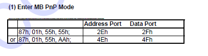
So far so good, and I understood what I'm doing.Where did you get the info to put the chip in mbpnp mode (and what's that?)?
*edit: got it at page 25 :
So I need CAh to 0x0E so I output on these 3 gpio, instead of input. They are always bit 1/2/3 for GP64/63/62 in each index? As in every bit 1 of each index (that's of interest in LDN 07) is always for GP64 let's say?
I don't understand Index C2h, 1 - simple I/O function, 0 - Alternate function. Isn't that defined in Index 27h?
I don't understand which Index deals with on/off 0/1 on the gpio pins.
Also, if I want to modify CAh index to set GP31-33 as output, I use let's say:./writeio64 2e ca ./writeio64 2f eOk, so I managed to get them to flash! I used the alternate function, set to 1hz rate, set as output and pulled high, otherwise it wouldn't work. Also used the location mapping table for which gpio to flash.
Now looking at using on/off. So far so good!
Got it!!!
So I'm using B2h index (LDN=07h) which is the gpio polarity, inverting/non-inverting. That way I can turn them on and off.
Going to check the second GPIO pin, and then check if I also have the third next to them.
Thank you so much for making me understand! Also your tools rock! Thank you very much for them!And here's the moneyshot:
Thing is, if I want to control them separately, I basically have to keep track of the other as I write to the memory.
So this is the shortest sequence:./writeio64 2e 87 ./writeio64 2e 01 ./writeio64 2e 55 ./writeio64 2e 55 ./writeio64 2e 07 ./writeio64 2f 07 ./writeio64 2e ba ./writeio64 2f 6 // 2 turns on GP31 and GP32 off, 4 turns GP31 off and GP32 on, 6 turns both on, 0 turns both off ./writeio64 2e 02 ./writeio64 2f 02Tried to make a bash script but if I use /bin/sh /root/script I get some errors:
#!/bin/sh
/bin/sh /root/writeio64 2e 87
/bin/sh /root/writeio64 2e 01
/bin/sh /root/writeio64 2e 55
/bin/sh /root/writeio64 2e 55
/bin/sh /root/writeio64 2e 07
/bin/sh /root/writeio64 2f 07
/bin/sh /root/writeio64 2e ba
/bin/sh /root/writeio64 2f 2
/bin/sh /root/writeio64 2e 02
/bin/sh /root/writeio64 2f 02
: not found /root/writeio64: 1: Syntax error: word unexpected (expecting ")") /root/writeio64: 5: Syntax error: Error in command substitutionworks with ./writeio64... tho
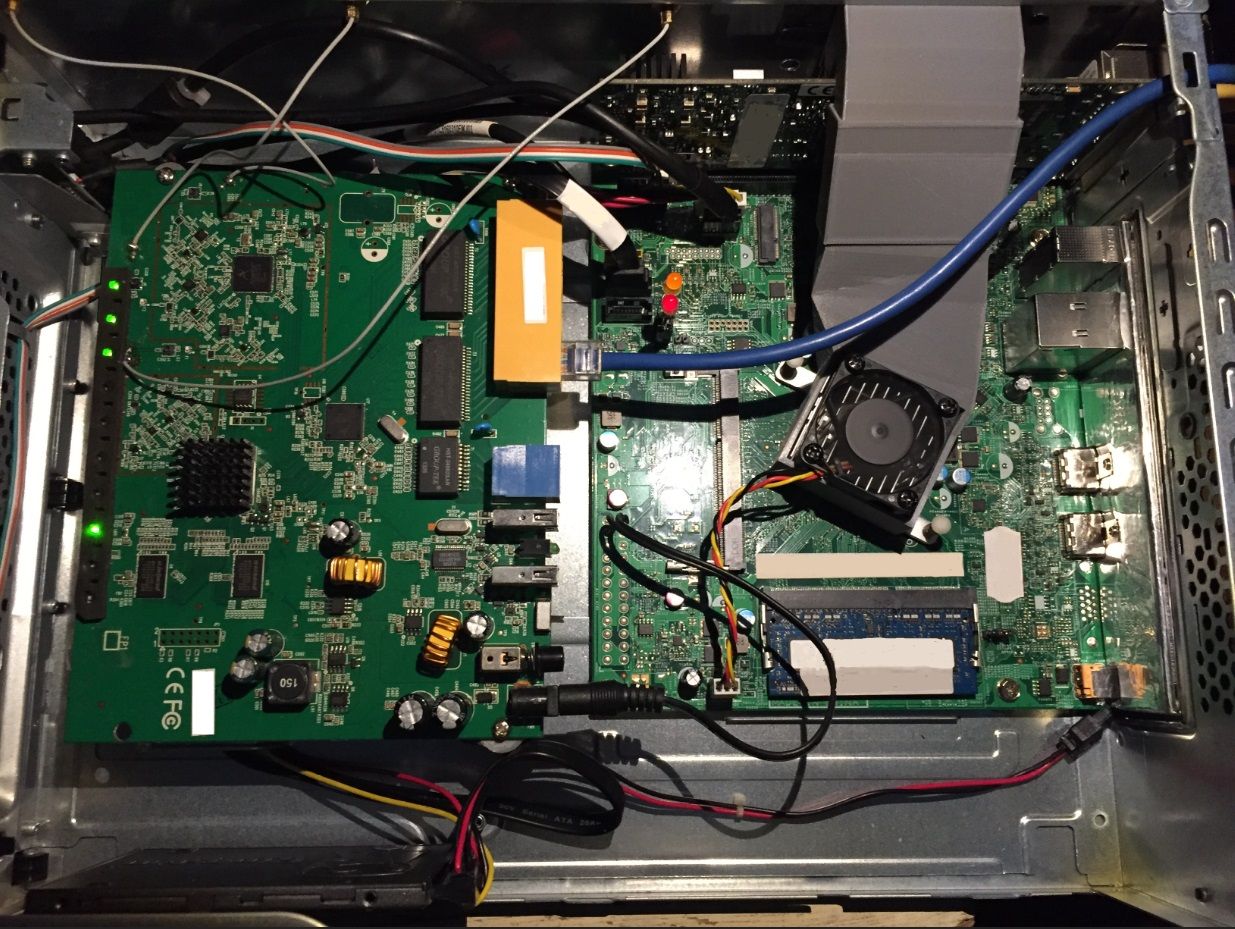
#!/bin/sh
./writeio64 2e 87
./writeio64 2e 01
./writeio64 2e 55
./writeio64 2e 55
./writeio64 2e 07
./writeio64 2f 07
./writeio64 2e ba
./writeio64 2f 6
./writeio64 2e 02
./writeio64 2f 02
As you can see in the picture, the wifi board is powered from 12V from the atx unpopulated socket. I checked the mosfets powering it and they are more than capable for the job. The PC had a 3.5" HDD, that I replaced for a 2.5" ssd. Issue is that even if I reboot the pfSense machine, the main caps from the wifi board keep it powered for the short time it takes the PC to power back on, and I can't reboot the wifi board by rebooting the pfSense machine. Also shouldn't be a problem as the wifi board is fused.
I think I'll use two relays and a timer for each board (two for wifi and two for raspberry) so I implement some kind of crude softstart with a resistor. PC's power supply is swiched and can deliver too much current. If I turn on the wifi board after the PC starts, I get a brownout and PC resets. Those wifi main caps draw large current at startup. Original power supply brick for the wifi was a linear transformer. Don't want to bust the pfSense machine. -
Nice!
Yeah the ITE chip is weird compared with Winbond and clones of that. I mean:
0: Input mode
1: Output mode
What drugs were they on that day?!

But also it doesn't have a register to directly set the output. Instead you set the default pull up or pull down and then set the invert register. Or at least that's what I did on the one box I have with one of these.
Setting the complete register using a hex value is a hack. If you look at 'real' code what you should do is use a bit-mask so you you are only setting whatever bits you needs to and others remain unchanged. I've never had to do that in that program I wrote as it only runs at boot. I'm not sure I've seen it done in a shell script rather than in C but it probably is possible.
You should only need to use ./ in the script if you're running from the command line and in that folder. Otherwise I have used just:
#!/bin/sh
/writeio64 2e 87
/writeio64 2e 01
/writeio64 2e 55
/writeio64 2e 55
....
Do you have a serial console between those boards internally?
Steve
-
Yes I was thinking at masking, just flipping the needed bit, but it works this way. With two GPIOs it's doable. More would become cumbersome.
There's only the ethernet cable linking the pfSense machine and the wifi board (it's a tplink wdr-4300 that I pulled out of it's enclosure and 3D printed some standoffs for the case) and it's running openwrt. Good enough for my needs.
I guess I could link them via USB but no need at the moment. -
Mmm, might be fun to connect the TTL serial header an the TPLink to that UART1 header on the Acer board. You'd have to check that is also TTL but it would give you much better access to OpenWRT.
Steve
-
that would be nice to explore.
I see a uart port on the wifi board:
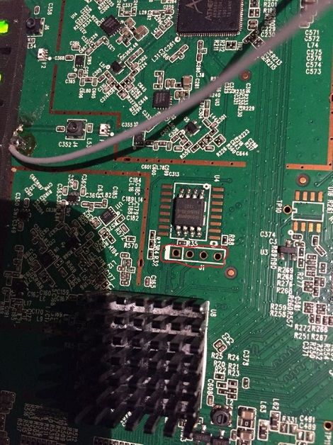
I mean I suppose it's one as it's near the eeprom.
I need to sniff both out and see if there's any relevant info.
Is there direct access to the UART of the Acer board? From freeBSD?
-
Yes, it would probably be:
cu -l cuau1 -s 115200Assuming cuau0 is an external serial port. But you could easily change that for whatever port it is.
You can also add a line to the remotes file so you can use 'tip' instead. You have to add a one-line script to replace it at each boot but it makes it very easy:
[2.4.4-RELEASE][root@pfsense.fire.box]/root: tip switch
connected

General Commands:
-----------------
Help/?: Get help on a group or a specific command
Up    : Move one command level up
Logout: Exit CLI

Command Groups:
---------------
System      : System settings and reset options
IP          : IP configuration and Ping
Port        : Port management
MAC         : MAC address table
VLAN        : Virtual LAN
PVLAN       : Private VLAN
Security    : Security management
STP         : Spanning Tree Protocol
Aggr        : Link Aggregation
LACP        : Link Aggregation Control Protocol
LLDP        : Link Layer Discovery Protocol
EEE         : Energy Efficient Ethernet
QoS         : Quality of Service
Mirror      : Port mirroring
Config      : Load/Save of configuration via TFTP
Firmware    : Download of firmware via TFTP
Loop Protect: Loop Protection
IPMC        : MLD/IGMP Snooping
Debug       : Switch debug facilities

Type '<group>' to enter command group, e.g. 'port'.
Type '<group> ?' to get list of group commands, e.g. 'port ?'.
Type '<command> ?' to get help on a command, e.g. 'port mode ?'.
Commands may be abbreviated, e.g. 'por co' instead of 'port configuration'.
>
Steve
-
I'll have a look at it this weekend.
Are there standard commands for controlling the wifi board? Or maybe chipset dependent?
*edit:
I found this:
https://github.com/freebsd/freebsd-wifi-build/wiki/TPLink-TL-WDR3600
Does this mean that freeBSD knows the chips? Mine has the same hardware. I don't need NAT or firewall. All that is managed from pfSense. -
Linking the com ports would give you access to OpenWRTs command line should you ever be locked out of it's network ports for some reason. So you can do there whatever OpenWRT will allow which is pretty much everything, the webgui is optional in OpenWRT. It doesn't mean pfSense would be aware of any of the wifi hardware on the TP-Link.
It would be interesting to try running FreeBSD on the TP-Link directly but I would expect significant effort there to get anything working and less functionality than OpenWRT. I would only try that as a project.
Steve
-
Ah yes, very useful to have access to OW from serial. I did lock myself out a few times and had to reset. Would they interact with eachother when they both boot up? I figure both are loading the eeprom's contents at startup.
I could put freeBSD but at this point I'm pretty happy with the features, especially since I have those GPIOs. I'll focus on the firewall rules for now. -
That link would be for a FreeBSD image that runs on the TP-Link instread of OpenWRT. You probably don't want to do that!
I would not expect any interaction between the com lines there. There should not be any output on com2 when pfSense is booting. It's never been an issue on that device with the build in switch for example.
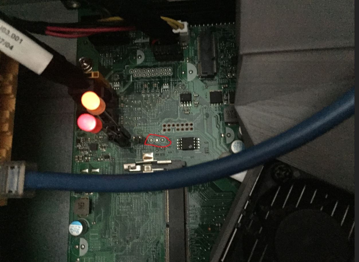
I would be very surprised in that header marked 'UART1' is actually connected directly to the eeprom. It's probably connected to the SuperIO chip. Accessing the eeprom would be via an SPI header almost certainly.
I have no way to know that for certain of course!
Edit: Looking again at the photo what's on that 2 pin header just next to the UART1 label? Also it looks like there is something shown as 'SPI1' which I would expect to be for accessing the eeprom.
Steve
Copyright 2025 Rubicon Communications LLC (Netgate). All rights reserved.