Help with 8 switch in a ring topology
-
-
@bingo600
they ask for fiber -
@kiokoman
Do they just have 1 fiber between floors , or are they in "Saving mode"
Actually they prob. have two fibers between floors.One path is bridged on every floor , making the long T <--> 15 fiber path.
The other is the "inter floor connection" you have on the drawing./Bingo
-
ok i have more intel..
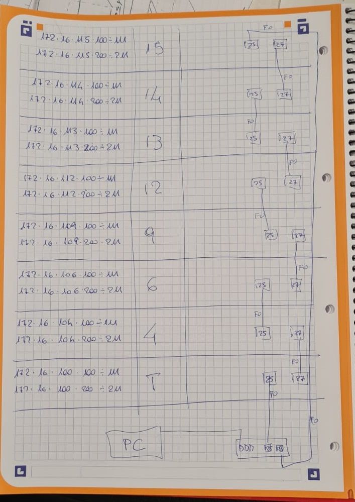
there are no pc, it's a network specifically for 168 IOT devices that can only do 10/100, distributed in 16 floors
it's one big flat L2
the assigned ips are there to better understand where the device are
so 172.16.104 is floor 4 - .100 should be east wing .200 west wing
172.16.112 is floor 12 and so on
iot device are there to measure pression and movement of the building (earthquake)
they send data to a server with a monitoring program and a mysql database
they send data only if there are something to report
the client specifically requested this ring configuration (an hospital) there is no way to change it -
@kiokoman
If it's a low volume IOT setup , then i see no issue in doing what you have described.Not best practice from a performance wise point.
But how much data will they push to the server ...RSTP would be preferred , but you would prob survive the 50 sec STP delay , as it's only on a switch uplink topology change it would be active.
As previously mentioned i'd prob. force the bottom switch to be STP Root.
Are you sure they will continue to use it as a flat L2 (single vlan) ?.
These IOT/HVAC nets have a nasty habit of being (mis)Used for other things at a later point.What i mean ... Should you Vlan enable the setup already on install.
And maybe just make 1 or 2 vlans for starters, and assign all edge/client ports to the IOT VLAN for now.That way they can (mis)Use it for some other low volume stuff at a later time, wo. major downtime.
Just a suggestion:
I'm not sure if this goes for RSTP too , but in the old days ... :I'd suggest you test a few DHCP clients (if DHCP is used for IOT) , by disconnecting the RJ45 , and reconnect it , or power off/on the device.
We have (in the old days) all been bitten by not setting "spanning tree portfast" , on an edge port. And have the STP delay take longer than the "Windows" DHCP timeout , giving DHCP timeout issues at times.I think it (portfast on cisco) might be called spanning tree edge on some switches.
/Bingo
-
@kiokoman said in Help with 8 switch in a ring topology:
they send data only if there are something to report
I would hope they send some sort of keep alive at some sort of interval even if its every 24 hours or something.. To just say - nothing to report..
If not what if something goes off line - and then there is some sort of event, and you miss the data because device has been offline for 3 weeks..
But that sure seems like low amount of data.. So yeah shouldn't be an issue..
edit: Ok still missing a piece of the drawing there, assumed those were stacked switches. But there is nothing actually showing connections so while the 1st floor listed and top have a connection to the bottom switch.. Those other switches are not actually showing a connection on how they could talk to the bottom switch.
-
I read the drawing as each floor (switch / stack) having a fiber comming from "top" , and another going to the one "below".
So each switch have 2 fiber connections , that would make a single floor failure survivable , except lowest (SPOF) , that feeds both paths.
Edit :
I read the 2 "boxes" on each floor , as representing the fiber interfaces in same switch/stack. Not 2 separate switches.
Else that drawing makes no sense./Bingo
-
@bingo600 said in Help with 8 switch in a ring topology:
I read the 2 "boxes" on each floor , as representing the fiber interfaces in same switch/stack
Well that makes much more sense ;) heheheh
I was thinking the same thing until mentioned east and west.. So I was thinking they were 2 switches one on each side of the floor ;)
-
@johnpoz said in Help with 8 switch in a ring topology:
I was thinking the same thing until he mentioned east ans west.. So I was thinking they were 2 switches on on each side of the floor ;)
That would leave some (most) IOT units "speachless"

But now that you mention east/west ... 100/200.
I hope not ..... Unless he's linking east/west via copper , and this is just showing the fiber patch./Bingo
-
Exactly - which was like what... So yeah if connections off the same switch on each floor then yeah makes sense and you have 2 paths in case of problem with 1 of the switches..
With very low bandwidth requirements - nothing wrong with doing it that way I guess. I would still have runs to each switch (if possible)..
-
@johnpoz said in Help with 8 switch in a ring topology:
I guess. I would still have runs to each switch (if possible)..
They prob haven't got the fibers for it.
This is prob. an addon , and most fibers are reserved/used for other stuff.See my edit in the post above ...
You made me doubt now .../Bingo
-
there is 1 switch on every floor. port 25 go to the switch below, port 27 go to the switch on the upper floor.
.100 ----copper ---> switch <---copper------ .200 port 25/27 up/down fiber
i will add a second switch to the SPOFthey are preparing all the switch in a lab to take the test and the first configuration
-
@kiokoman
So everything will reside in the 172.16.x.x/16 range , including switch mgmt ?All in a single "default vlan" ?
/Bingo
-
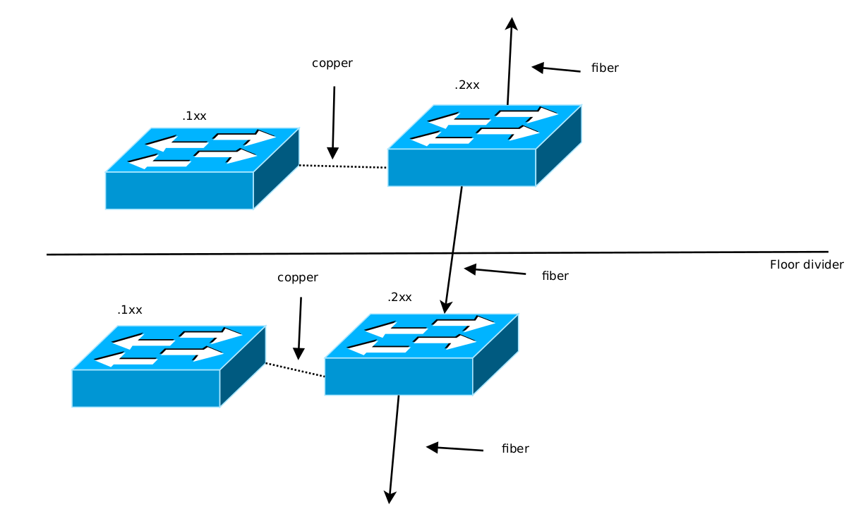
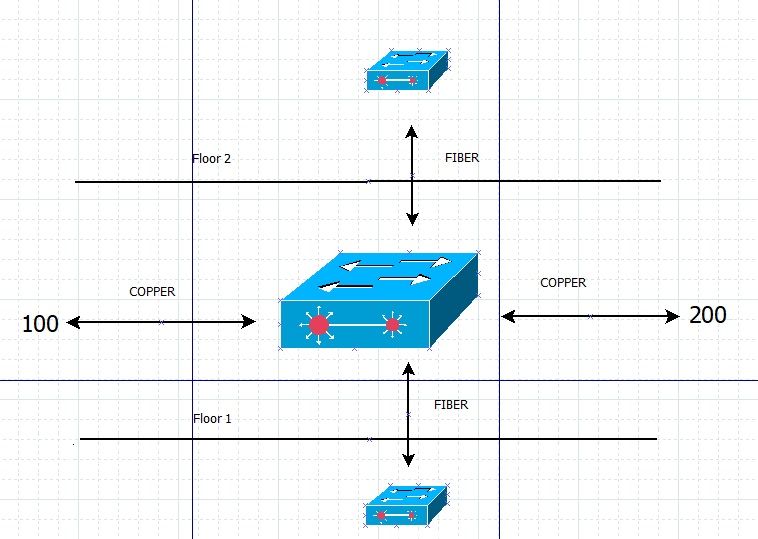
Is this a "floor layout" ?

/Bingo
Made with the Free drawing tool - Dia - http://dia-installer.de/
Quite intuitive , I installed dia + dia-shapes
kioko.dia.zip -
-
Does that mean there's 3 switches on each floor ?
The "Red dot" fiber connected switch , and then the copper connected IOT switches 100 & 200 ??/Bingo
-
@bingo600
i selected a random picture from your program...
there is 1 switch x floor -
Ahh so that was just a "Dia drawing test"


