Help with 8 switch in a ring topology
-
@johnpoz said in Help with 8 switch in a ring topology:
I was thinking the same thing until he mentioned east ans west.. So I was thinking they were 2 switches on on each side of the floor ;)
That would leave some (most) IOT units "speachless"

But now that you mention east/west ... 100/200.
I hope not ..... Unless he's linking east/west via copper , and this is just showing the fiber patch./Bingo
-
Exactly - which was like what... So yeah if connections off the same switch on each floor then yeah makes sense and you have 2 paths in case of problem with 1 of the switches..
With very low bandwidth requirements - nothing wrong with doing it that way I guess. I would still have runs to each switch (if possible)..
-
@johnpoz said in Help with 8 switch in a ring topology:
I guess. I would still have runs to each switch (if possible)..
They prob haven't got the fibers for it.
This is prob. an addon , and most fibers are reserved/used for other stuff.See my edit in the post above ...
You made me doubt now .../Bingo
-
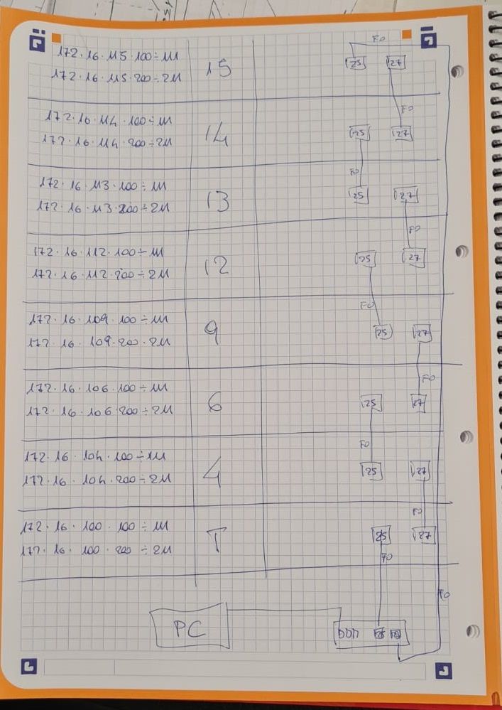
there is 1 switch on every floor. port 25 go to the switch below, port 27 go to the switch on the upper floor.
.100 ----copper ---> switch <---copper------ .200 port 25/27 up/down fiber
i will add a second switch to the SPOFthey are preparing all the switch in a lab to take the test and the first configuration
-
@kiokoman
So everything will reside in the 172.16.x.x/16 range , including switch mgmt ?All in a single "default vlan" ?
/Bingo
-
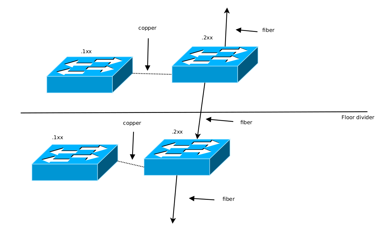
Is this a "floor layout" ?

/Bingo
Made with the Free drawing tool - Dia - http://dia-installer.de/
Quite intuitive , I installed dia + dia-shapes
kioko.dia.zip -
-
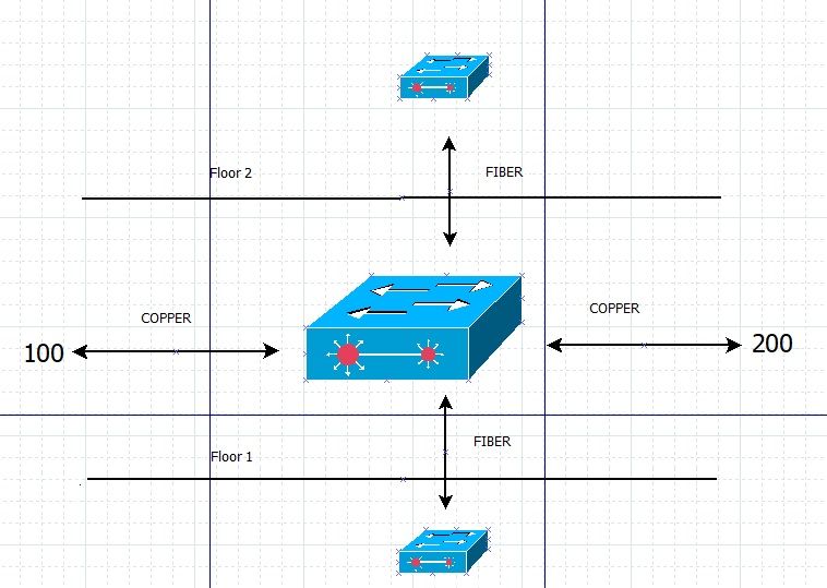
Does that mean there's 3 switches on each floor ?
The "Red dot" fiber connected switch , and then the copper connected IOT switches 100 & 200 ??/Bingo
-
@bingo600
i selected a random picture from your program...
there is 1 switch x floor -
Ahh so that was just a "Dia drawing test"


